Pill Dispenser
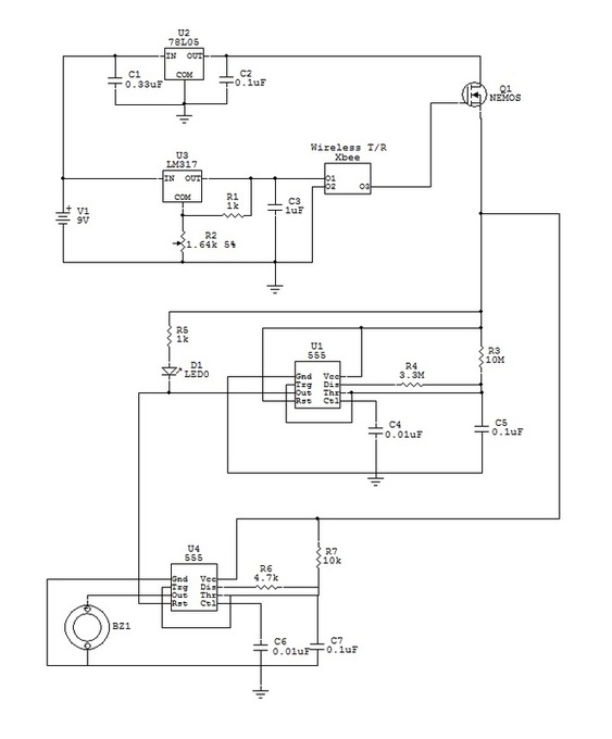
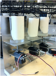
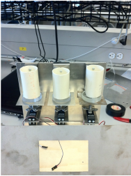
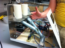
We altered our design for the pill dispenser many times after consulting with the technicians. We finalized the design to contain three hoppers which will contain the pills. The hoppers were made with 2" PVC material. Each hopper is 80mm long and directly below is the acrylic puck which is comes in 8mm, 10mm and 12mm sizes according to the pill the patient is taking. The puck is attached to a threaded rod which is controlled by a servo motor. Once the puck is moved 180 degrees to a position where it can collect the pill, it will move 180 degrees in the opposite direction and drop it on the metal plate below it which will allow it to flow down the pipes and into the area where the patient will collect his/her medication.
Electrical Design
To achieve our design goals, we needed the following major components.
The choice of the keypad and LCD was simple. We wanted something that can be operated easily by senior citizens. Because seniors sometimes have trouble seeing small letters, we picked a 128 x 64 graphic LCD by Newhaven Display with a white LED backlight. This allowed us to display the messages clearly on the LCD for the user. Our keyboard choice followed the same principle of simplicity and usability. We picked a 16-key keypad that includes keys A-D, 0-9, *, and #. It had enough keys to satisfy the functional need of the device, and it should not too complicate for seniors to operate.
To rotate the medication bins, we used three Parallax standard servo motors with 0-180 degrees of operation, 43.1 oz-in of torque at 6V, and 4-6V of input voltage. We chose these mainly because they were powerful enough and had a wide enough operation angle for rotating the mechanical dispenser disk. Also, since they operated by pulse-width modulation (PWM), we could apply our previous experiences, and that made programming the microcontroller easier. To power these motors, we used a LM7805 together with the appropriate capacitors to regulate the voltage to five volts.
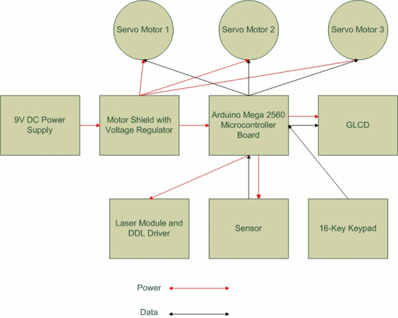
Please see figure below for a block diagram of the system. The red arrows represent power flow, and the black arrows represent data flow.
- LCD to display messages, clock, and timers.
- Keypad for user to choose medication, set alarms, and change clocks.
- Three servo motors to turn the mechanical device that will dispense the pills.
- Motor shield to regulate the DC power supply voltage.
- DC Power Supply
- Microcontroller with wireless transmitter.
- Buzzer alarm with wireless receiver.
- Sensor to detect the presence of a pill in the dispenser.
The choice of the keypad and LCD was simple. We wanted something that can be operated easily by senior citizens. Because seniors sometimes have trouble seeing small letters, we picked a 128 x 64 graphic LCD by Newhaven Display with a white LED backlight. This allowed us to display the messages clearly on the LCD for the user. Our keyboard choice followed the same principle of simplicity and usability. We picked a 16-key keypad that includes keys A-D, 0-9, *, and #. It had enough keys to satisfy the functional need of the device, and it should not too complicate for seniors to operate.
To rotate the medication bins, we used three Parallax standard servo motors with 0-180 degrees of operation, 43.1 oz-in of torque at 6V, and 4-6V of input voltage. We chose these mainly because they were powerful enough and had a wide enough operation angle for rotating the mechanical dispenser disk. Also, since they operated by pulse-width modulation (PWM), we could apply our previous experiences, and that made programming the microcontroller easier. To power these motors, we used a LM7805 together with the appropriate capacitors to regulate the voltage to five volts.
Please see figure below for a block diagram of the system. The red arrows represent power flow, and the black arrows represent data flow.
Sensors Design
We needed a sensor that can detect a medicine pill after it has been dispensed from one of the three bins. For this sensor, we went through a few different designs. We researched and tested string gauge based load cell, double plate capacitor sensor, and an infrared proximity sensor. Finally, we decided to go with a laser and CdS photocell design [6,7]. We used a 5mW red laser diode and a lens we got from a laser pointer to produce the laser [8]. To drive the laser diode, we used a LM317 as current regulator to regulate the current to 40mA [8]. Also, we used a 1µF capacitor and a diode to protect the laser diode from voltage spikes and reverse voltages.
When the laser was hitting the photocell, its resistance decreased. If the beam of laser was blocked by a medicine pill, its resistance changed from an approximate maximum of 450Ω to a minimum of 1.7kΩ. Because the change was very significant, we used the CdS photocell in series with a 230Ω resistor to create a voltage divider with its junction voltage changing from 2.5V to 3.5V. We used this property together with an N-Channel MOSFET, a LED, and a 100Ω resistor to create a simple indicator that turns on when there is a medicine pile detected [5]. The microcontroller read the voltage before the LED and turned the wireless wrist band on when it was Vcc, and turned the wireless wrist band off when the voltage dropped to 2V.
When the laser was hitting the photocell, its resistance decreased. If the beam of laser was blocked by a medicine pill, its resistance changed from an approximate maximum of 450Ω to a minimum of 1.7kΩ. Because the change was very significant, we used the CdS photocell in series with a 230Ω resistor to create a voltage divider with its junction voltage changing from 2.5V to 3.5V. We used this property together with an N-Channel MOSFET, a LED, and a 100Ω resistor to create a simple indicator that turns on when there is a medicine pile detected [5]. The microcontroller read the voltage before the LED and turned the wireless wrist band on when it was Vcc, and turned the wireless wrist band off when the voltage dropped to 2V.
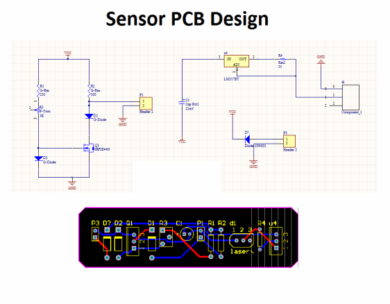
Printed Circuit Board
We designed our PCB using Altium Designer. The circuits that we placed on the circuit for were the circuits for the laser diode and photoelectric sensor. After creating our design for our PCB, we had them produced by DYCO Circuits. The schematic for our circuits and the PCB can be seen below.
Wireless Wrist Module
The wrist module was simply a wireless alarm with a flashing LED and a beeping piezo buzzer. The microcontroller turned the wrist module on an off depending on whether there was a medicine pill detected by the sensor or not. The Xbee wireless receiver required a strict 3.3V to operate. The transmitter XBEE was configured as a ZIGBEE COORDINATOR AT and the reciever as a ZIGBEE ROUTER AT. We only used one output pin on the reciever to control an N-Channel MOSFET. To supply the required voltage, we used a LM317 adjustable voltage regulator. Its output voltage was controlled by the following equations. [9]
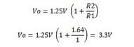
The capacitor is there simply to improve the transient response. We used two LM555 timers to the LED and buzzer. To power the circuit, we used a five volts regulator with some capacitors to minimize voltage spikes. The MOSFET controlled by the Xbee receiver turns the power on and off to the alarm circuit and thus creating a wireless alarm. We used two LM555 timers in 50% duty cycle oscillator mode to turn the LED and buzzer on and off. [10]